取消
Quantity
Price
Total price
1
$54.1590
$54.1590
10
$42.3150
$423.1500
100
$40.1940
$4,019.4000
| TYPE | DESCRIPTION |
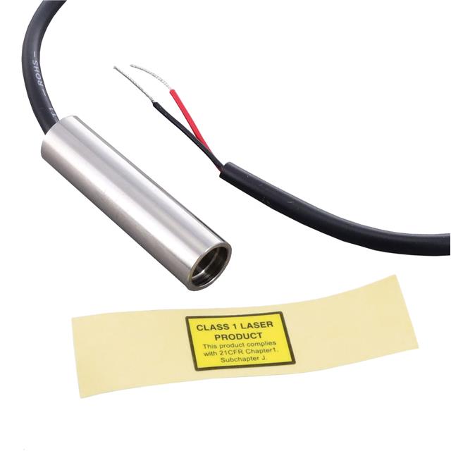
| Mfr | Quarton, Inc. |
| Series | VLM-635-60 |
| Package | Bag |
| Product Status | ACTIVE |
| Power (Watts) | 0.39mW |
| Package / Case | Cylinder (10.0mm Dia) |
| Wavelength | 638nm |
| Current Rating (Amps) | 40mA |
| Voltage - Input | 3 ~ 6VDC |